Circuit Innovations
Taking your electronics ideas and turning them into reality
| Home |
| Design Service |
| Kits and Products |
| Film and Television |
| Beginners Corner |
| Surplus Stock |
| Price / Ordering Info |
| Contact Us |
| Terms and Conditions |
| Links |
| About |
|
Circuit Innovations 24 Leasmires Avenue Easingwold York. YO61 3DU UK |
 |
| Kits and Products > 555 / 556 General Purpose Timer Circuits |
|
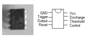
The picture to the right shows one of the most versatile integrated circuits that has ever been built. It may look quite small and unassuming but its versatility has led to whole books of useful circuits being published. The circuits below give the basic operating modes of the 555 timer ic. |
|
|
Monostable Mode In this mode the 555 is used as a single-shot timer to produce an output of a fixed duration. The time period is set using one capacitor and one resistor. The time period is started by applying a low pulse to the trigger input. The output pin then goes high for the duration of the time period. The time period may be interrupted by applying a low pulse to the reset pin. If reset is not being used it is normally connected to the +ve supply. The time delay is given by the formula t = 1.1 RC where R is in ohms and C is in Farads |
|
|
Astable Mode In this mode the 555 is used as an oscillator. The oscillator frequency and mark / space ratio is set using one capacitor and two resistors. The reset pin may be used to stop the oscillator. The oscillator frequency is given by: f = 1.44/((R1 + 2R2)C) The time period is given by : Output High th = 0.693(R1+R2)C Output Low tl = 0.693R2C |
 |
|
Decoupling The power supply is usually decoupled by a capacitor of 10 - 100uF. The control voltage on pin 5 is decoupled by a smaller capacitor of about 10nF. Some variants of the 555 do not require a cap on this pin. A general rule of thumb is that if your circuit suddenly starts behaving unpredictably, put a cap on pin 5.
|
|
|
|
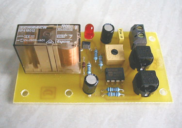
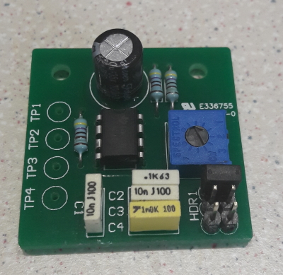
Oscillator Kit | |
|
|
 |
 |
|
556 Timer The 556 consists of a pair of 555 timers in one package. The two timers work independently and only share common power supply connections. A typical example of a 556 circuit is shown here. The circuit drives a piezo sounder to provide a pulsed bleeping sound (similar to the reversing warning on many vehicles). One half of the 556 is running at the resonant frequency of the piezo sounder, around 3-4KHz, while the other half is running at a very low frequency of about 0.5Hz. The output from the low frequency oscillator is connected to the reset pin of the high frequency oscillator to modulate the output and turn the bleep on and off. |
|